【Abstract】This paper analyzes the failure of the design of the die-casting mold, and expounds the key elements that should be paid attention to during the design process of the die-casting mold. When simulating the runner system of other successfully designed die-casting molds, it must be based on actual conditions. Design, modification and improvement of the structural characteristics of the die-casting parts; especially when copying the molds, the elements that are temporarily incomprehensible are still retained as a criterion.
[Keywords] design failure, die casting mold runner design, imitation
CLC number: TG249.2 Document code: B
1.Foreword
Die-casting production is inseparable from die-casting molds. The quality of molds directly affects the normal production of die-casting, as well as the economic benefits of enterprises, the wages of employees, and so on. A well-designed die-casting mold can maximize the production efficiency of the equipment, effectively reduce the energy cost of die-casting production, and reduce the scrap rate of die-casting parts. Experience has shown that a well-designed die-casting mold mainly depends on its runner system. Whether the design was successful. The runner design of the die-casting mold is the key to a die-casting mold.
The normal die-casting production depends firstly on the correct position setting and shape size of the sprue system. When the production weight is large, the wall thickness is very different, the shape is complex, and the compactness of the structure, surface quality and process quality are strictly required, the pouring is carried out. These design parameters of the track need to be carefully designed. In any case, it is impossible to compensate for the other die casting parameters due to the improper influence of the sprue system setting on the quality of the die casting product.
The design of the cast-in-place sprue system requires a thorough analysis of the structure of the casting and the various requirements of the customer, and it is determined that these requirements are basically met. The general process for designing the sprue system is:
a) select the location of the gate;
b) consider the direction of the flow of the guiding metal;
c) the number of shares of the gate;
d) set the shape and size of the runner;
e) Determine the cross-sectional area of the ingate.
Although the design of the sprue system is simple to divide the above steps, some changes in each factor will cause a large change in the design of the gating system. Except for the cross-sectional area of the ingate, a better P-Q2 chart can be made. In addition to the confirmation, the consideration of several other factors still depends on the personal experience and knowledge of the mold designer; for the die casting, there are very few situations that can fully satisfy the ideal gate position setting, which is often “guaranteed the main requirements. The principle of taking into account the secondary link is carried out. In the actual mold design, most of the experience is to make the structural design of the sprue system. Therefore, the imitation and improvement of the casting system of the successful mold in the past becomes one. An indispensable design method.
However, in the process of imitating the old mold runner system, if it can not be used flexibly, then the case of imitating failure in the actual design is not uncommon. The following is a brief discussion of a real case, so that we can get it from it. Some inspiration, in the future mold design to take the lead, improve the success rate of mold design.
2. Example analysis
2.1 Steering shell copying mold sprue system imitation
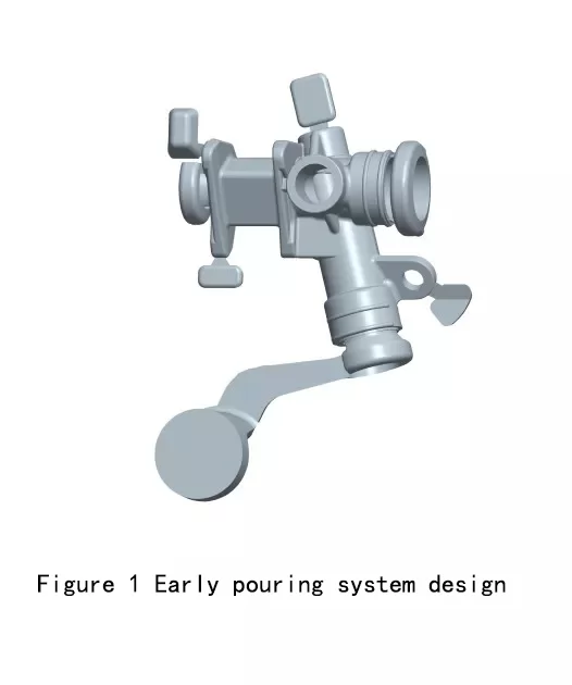
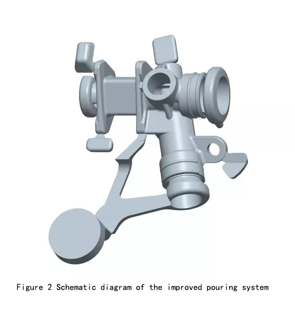
Figure 1 shows the casting sprue design of a car steering gear housing. This sprue design is an early design structure. Due to the use of a circular main runner for filling, the product is basically well formed, but due to the core The partial wall thickness of the sub-intersection is thicker, and there is a large shrinkage hole at the center. The customer proposes rectification requirements. To solve this quality problem, after the simulation filling of the mold pouring system, we change the sprue system of the mold to The structure shown in Fig. 2 adds a small auxiliary runner to the thick part of the casting without affecting the appearance of the product. After the actual production experiment, the internal shrinkage of the thick part of the casting is obtained. Great improvement, product quality fully meets the needs of customers. Since then, the design of the casting system of this product has basically not changed. This die-casting mold has been designed and produced more than ten pairs, basically belonging to the shaped sprue design. In this way, these mold structures have never been changed too much in the process of copying, only to the extent that the local mold corners and the mold strength are insufficient. Designed to improve production quality problems found.
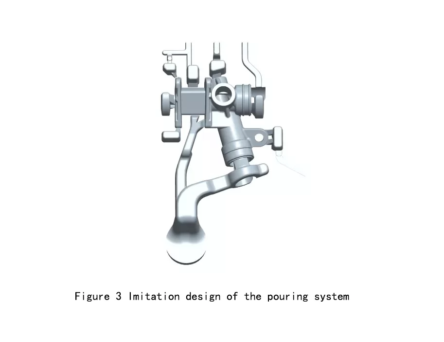
For various reasons, a new mold manufacturer was replaced to make a replica mold. The product picture of the newly designed mold production is shown in Figure 3. In the actual die-casting production, there was a quality problem:
1) poor product molding;
2) The internal part of the product is severely constricted;
3) The internal quality is reduced after machining;
4) The output of the class decreases, the main reason is that the spraying time increases, otherwise, the local sticking mode is cracked;
From the photograph of the casting (shown in Figure 4), the original designed auxiliary runner was completely turned into the main runner during the filling process of the molten metal, and the original main runner became the auxiliary pouring. The road also affects the normal filling of the mold. Since this product is a very mature casting, there is a mature die-casting process that can be used for reference. From the point of view of change, in order to solve these quality problems, it is necessary to find the reason from the mold design. Due to the change of mold manufacturers, there are still some differences in the design concepts of mold designers from various manufacturers. Although it is a set of copy molds, designers will more or less incorporate their own design concepts into new molds during the design process. Go in the design.
In the habitual design thinking, the main channel opened on the diverting cone is vertically upward, and not obliquely pointing in the direction of the inner gate. Therefore, when the grate is opened on the diverting cone, the new mold naturally According to the designer's experience, it is vertical upwards, and the direction of the slanting direction is not too much. Therefore, when the gate is opened on the diverting cone, the new mold naturally follows the designer's experience. It becomes a vertical upward mainstream channel; as we all know, for the die-casting flow channel, each flow turn will bring a large energy loss, and at the same time, due to the inertia of the molten metal filling, the flow is the most in the straight line direction. Filled first, the flow rate will be changed only if the current side fill resistance is increased.
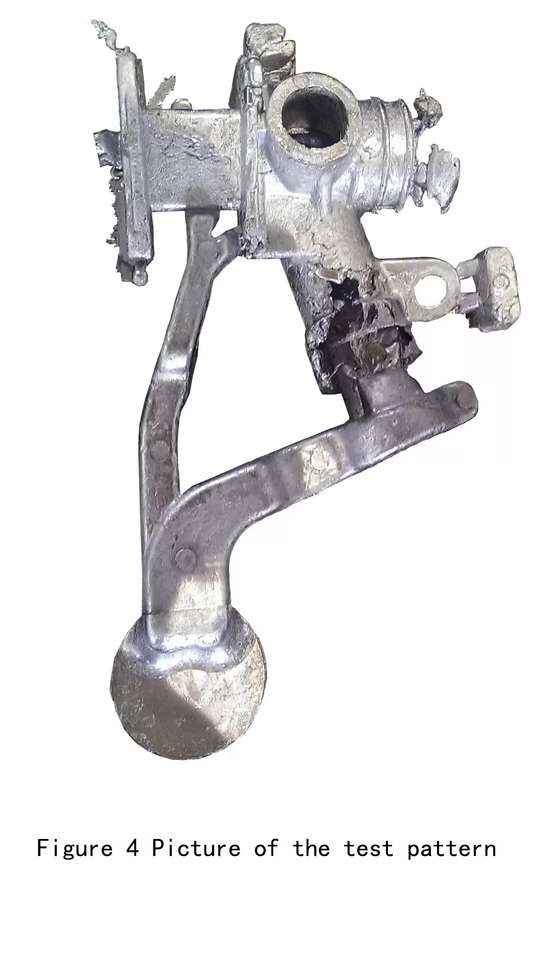
The newly designed main channel has a 90° turning point, and the auxiliary flow channel is just in the straight line direction. Then, in the process of filling the molten metal, it is first filled by the auxiliary runner, and then filled from the main runner. The phenomenon, from the actual production of the sample (shown in Figure 4), the entire filling process is basically done by the auxiliary runner, the main runner failed to fill.
2.2 Design changes to the drain system
In the design of the drainage system, the original design scheme is basically imitated. However, when designing the left side core of the product, it may be in the difference of design habits. The new design has made a small change. Some of the annular slag packages were changed to two separate small slag packages (as shown in Figure 5). This small change does not seem to have any effect on the casting.
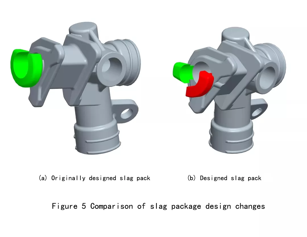
In the actual production of castings, it also failed to attract the attention of relevant personnel, until the customer's paper complaints caused the problem caused by this design change to be leaked; originally, the customer found that some products were internally lost during the machining process. Into the slag package, affecting the processing of customers! This is a problem that has never happened in the past years; the size of the original slag bag is larger than the hole diameter of the steering gear housing. The design change of the slag bag makes the size of one slag bag smaller and the outer shape smaller than After the aperture of the steering gear housing, in the subsequent production process, the slag collection package is dropped into the hole inside the product and stuck in the hole.
2.3 mold rectification treatment
According to the production situation of the mold, the corresponding rectification treatment must be carried out, and the mold modification should be carried out according to the original mold design scheme, so that the design of the sprue system becomes more reasonable and smooth, and the filling of the molten metal is facilitated, and the mold is solved. The problems in small batch production make the product quality meet the needs of customers.
The problem that the small slag package falls into the product hole can only be solved by connecting the two slag inclusions and increasing its outer dimensions.
3. Conclusion
Through the above example analysis, we can understand that the success factor that really determines the design of a pair of molds lies in the details of the mold design. The big principles are almost universally known, but in actual application, the success or failure is one-minded, each person’s knowledge level, right The understanding and understanding of the sprue system determines the success or failure of a pair of molds.
Copyright statement: The content of the article is extracted from the network. If there is any infringement, please contact us to delete it!


.png)


.png) +86-574-83036520
+86-574-83036520 +86-574-83008051
 sales@innovaw.com

.png)

.png)
.png)
.png)

.png)
.png)
.png)


.png)

