In addition to the structural characteristics of the die-casting part, the design of the die-casting mold needs to determine the size of the gate. It is also necessary to design the size of the gate by preliminary determination of the die-casting process parameters (filling time, filling speed, etc.). The flow, flow and junction of the aluminum liquid are controlled by different flow guiding methods. It provides a basis for the location determination of the overflow system and also provides a basic guarantee for the overflow system to maximize its effectiveness. This also provides a fundamental guarantee for the production of quality products.
Of course, the reasonableness of the mold structure is also one of the decisive factors affecting product quality. But this topic is not discussed here, so we only discuss the design of the gating system.
First, the flow of the design of the pouring system
1. Analyze 3D.
2. Determine the die casting process parameters.
3. Check if the selected die casting machine can meet the requirements.
4. Runner design.
Second, the specific steps of the pouring system design
Take the following disc as an example:
|
Material: |
ADC12 |
average wall thickness: |
3.27 (mm) |
|
Weight: |
451.09 (g) |
Filling time: |
0.034 (s) |
|
Vertical projection area: |
27220.6 (mm2) |
Filling speed:
|
36 (m/s) |
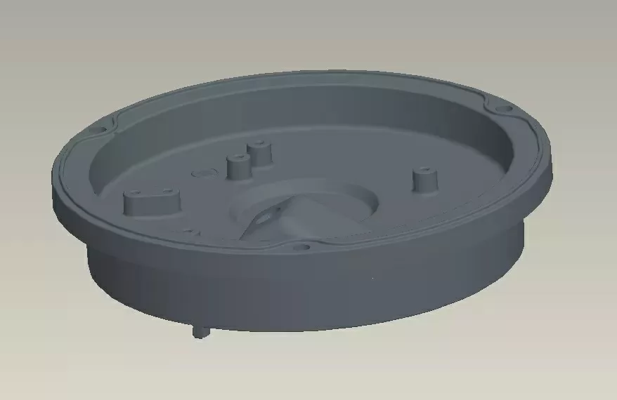
A
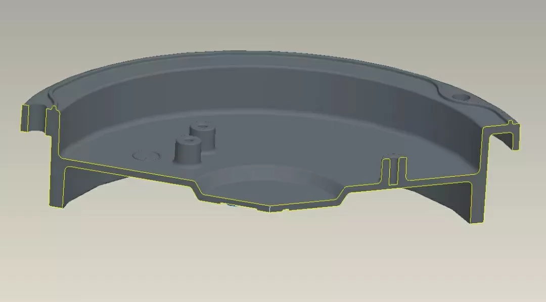
B
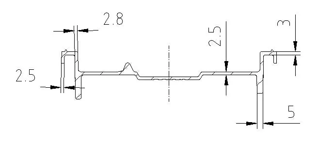
C
Part features:
1. The wall thickness is not uniform. From the outside to the inside, the wall thickness is from 2.5 mm → 3 mm (widening) → 2.8 mm (narrowing) → 2.5 mm (central narrowing) or 5 mm (mutation wide).
2. The middle is a thin wall plane.
3. The periphery of the boss will direct the aluminum liquid directly below the inner ring, and its 5mm width will easily attract the aluminum liquid.
(II) Determining the die casting process parameters:
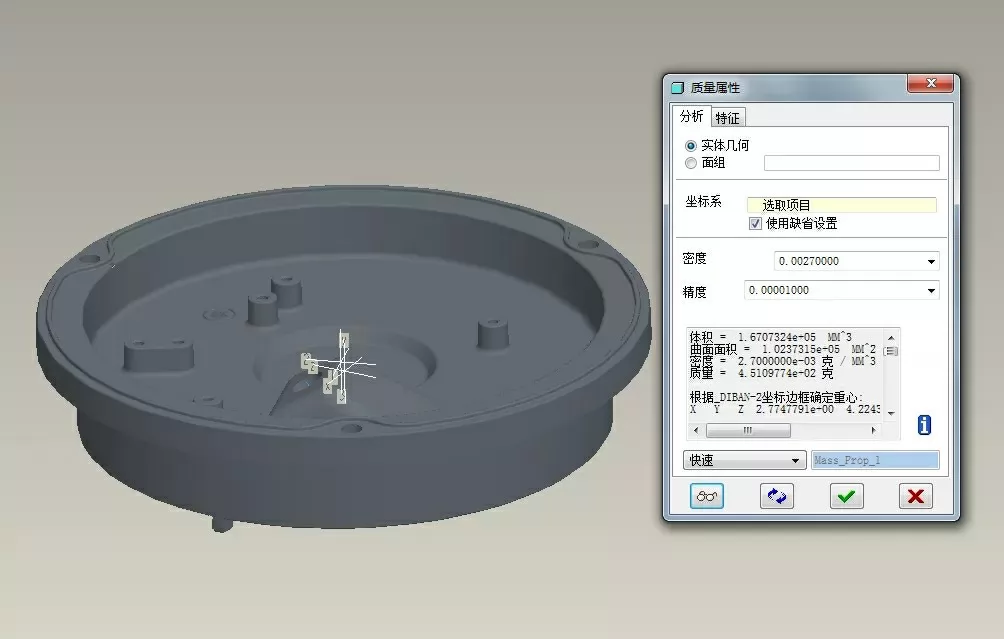
1. Determine the vertical projected area of the part. (measured directly in software)
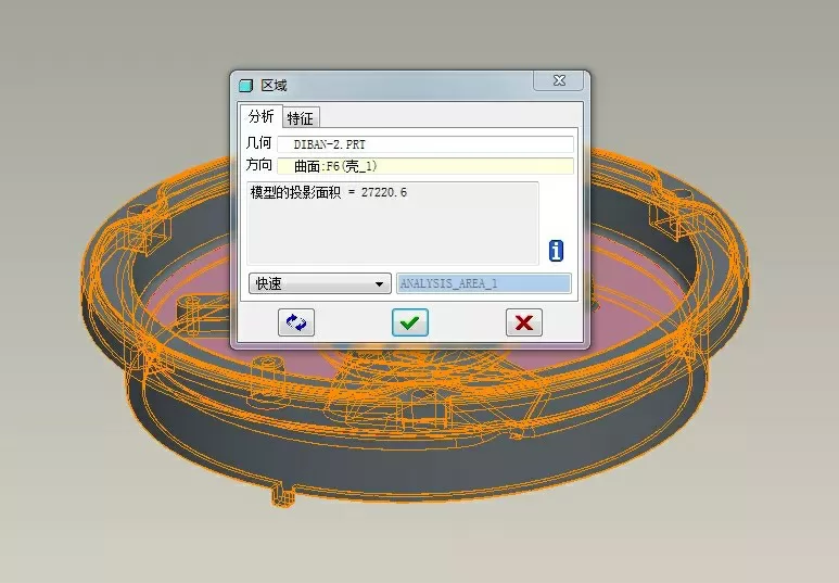
D
E
F
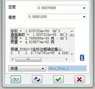
2. Determine the weight of the part. (measured directly in software)
3. Determine the average wall thickness of the part:
General design manual calculation method

b1, b2, b3... wall thickness of a casting
s1, S2, S3... The wall thickness of the casting is the area at b1, b2, b3
Simplified algorithm
Average wall thickness of the part (h) ≈ solidification modulus M × 2
Solidification modulus M = volume of the part (V) 曲面 surface area of the part (S)
example:

4. Determine the fill time and speed of the part:
Generally can be found directly from the design manual.
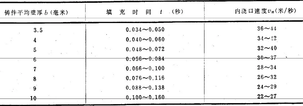
It can be found directly from the design manual. In order to meet the needs of filling flow, it is recommended to take a small value of the speed in the table under the premise that the energy provided by the die casting machine is relatively abundant. That is, filling time: 0.034(s) filling speed: (36m/s)
Empirical formula:
Filling time (t) = average wall thickness of the part × 0.0125 (S)
Example: t=3.27×0.0125=0.04(S)
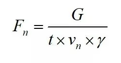
Fn - inner gate cross-sectional area (cm2)
t - fill time (s)
G——casting weight (g)
Vn - filling speed (cm/s)
γ- aluminum alloy liquid specific gravity (2.4g/cm3)

Check the energy reserve of the die casting machine:

Fn - inner gate cross-sectional area (cm2)
Fc - punch cross-sectional area (cm2)
Vn - filling speed (cm/s)
Vc - punch speed (cm / s)
Vc generally takes 400-420 (cm/s) as the upper limit.
Usually the upper limit of the model is marked as idling. And the premise is that the machine is new. After comprehensive consideration of various aspects such as machine loss, and verification over the years, it is reasonable and safe to take 400-420 (cm/s) as the upper limit.
example:

Substitute

282.5<400 (cm/s)
If the filling speed needs to be increased to 44 (m/s)

345.3<400(cm/s)
Conclusion: The energy storage of the punch speed is sufficient
6. Check the clamping force of the die casting machine:

FL - clamping force (tons)
Pg - injection pressure (bar)
Pz - increase pressure (≈2.5Pg)
St - product projection area (cm2)
Sq - the projected area of the runner and slag bag (cm2)
Vn - filling speed (m / s)
g——gravity acceleration (9.8m/s2)
γ- aluminum alloy liquid specific gravity (2.4g/cm3)
Experience value:

example:
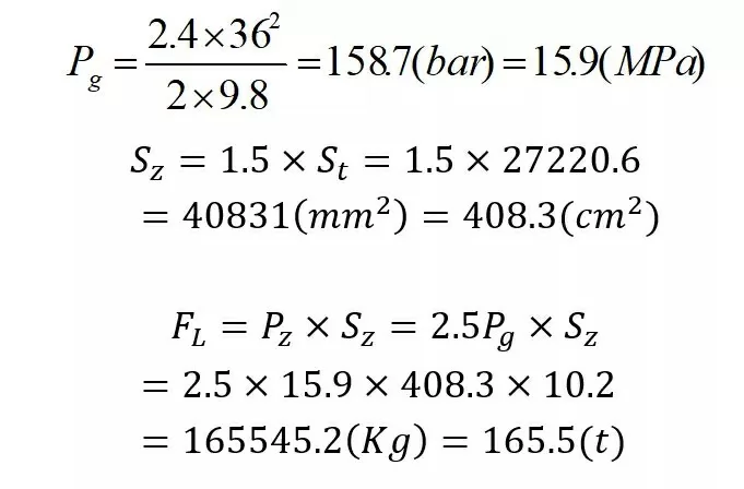
1bar = 0.1 MPa (Mpa) 1 MPa = 10.2 Kg / cm 2
(III) flow channel design
G
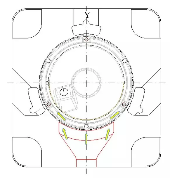
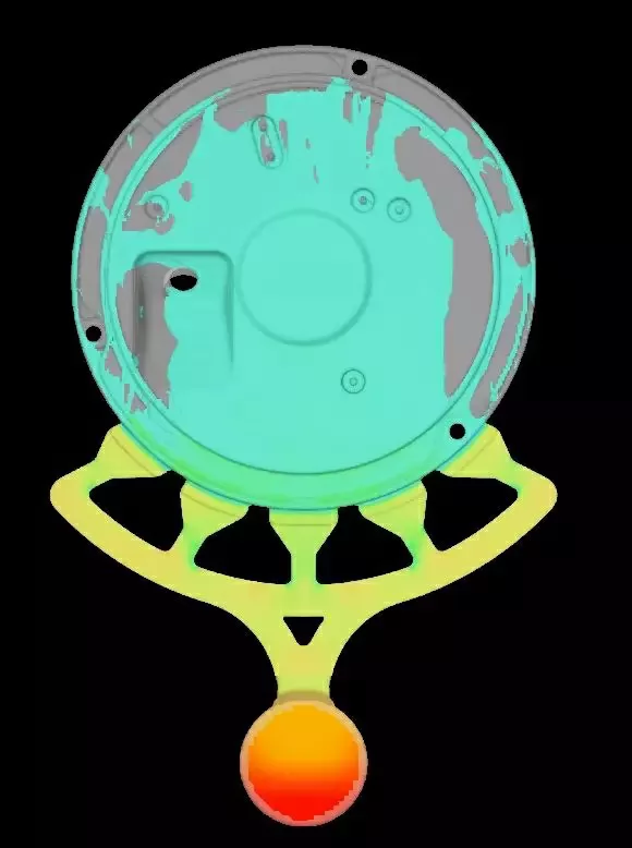
Although the old flow path has a strong directivity, when the aluminum liquid turns over the boss around the periphery, it is still filled in the direction of Y. In this way, it will inevitably be blocked by the next cavity wall. The result is that part of it is separated and left and part is forced to go down. There is little or no aluminum liquid that can run into the middle of the thin wall. The middle thin wall becomes the final filling position, so it is difficult to avoid the situation of trapped air. Then, it is only natural to produce good products.
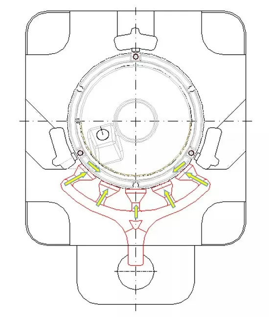
The new flow path also has a strong directionality, but when the aluminum liquid turns over the boss around the periphery, it blocks the next cavity wall. Direct the aluminum liquid to the inside. Together with the aluminum liquid that came in from the inside gate, it rushed inside. Since the two streams meet in the middle of the inner side, as the aluminum liquid on both sides continues to follow up, the middle thin wall becomes the least resistant area. In the case where the two streams are opposed to each other and squeezed, the liquid flow is forced into the intermediate thin wall. As the intermediate thin-walled fill area increases, the filling resistance will continue to increase. Similarly, the reaction force to follow up the aluminum liquid on both sides will also increase. When the reaction force increases to a certain extent, part of the aluminum liquid will break away from the mainstream, return from the gap next to it, start to fill the sides, and meet with the aluminum liquid overflowing in the middle thin wall, and then complete the whole circle The filling of the disc.
H
The success of this runner also depends on the adjustment of the die casting process parameters. Including: the ratio of the speed of the first speed and the second speed; the injection speed; the injection pressure. And other such as: mold discharge system; mold structure; mold temperature; die casting liquid temperature and other factors control.
1. Determine the location and form of the feed
The size of the gate area has been calculated previously. The main goal now is to design the gating system according to the filling sequence, flow direction required by the characteristics of the product, and the selection of the flow path form that can meet the above requirements.
2. Number of stocks to be imported:
In general, it is divided according to the area of the gate. But because each product has its own characteristics, the required filling state is naturally different. Therefore, the specific number is divided by the goal of being able to obtain an ideal filling state. Sometimes the ideal filling state is obtained even by increasing or decreasing the total area of the ingate (ie increasing the number of strands). When adding, it is necessary to consider whether the diameter of the original selected cylinder can still meet the requirements (such as the punch speed, etc.); when reducing, it is necessary to check whether the clamping force of the die casting machine is sufficient.
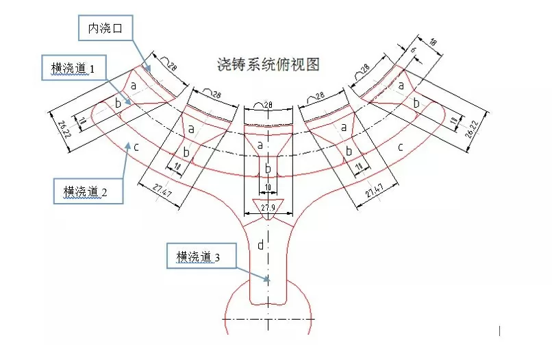
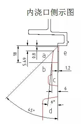
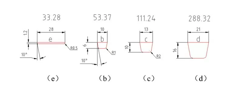
3. Ingate (position, shape as shown in Figure K-(e))
Ingates are generally approximately rectangular. The size of the fill flow is mainly controlled by its area.
4. Sprue 1 (position, shape as shown in Figure K-(b))
The runner 1 includes a lead-in zone (b) and a transition zone (a). The lead-in area controls the flow direction, and the transition area controls the flow state. The shape of this area is different and can produce a variety of different flow patterns.
Leading zone (b) section (as shown in Figure K-(b)). Its cross-sectional area is 1.5 to 2.5 times that of the gate. Note: ADC12 takes 1.5; ADC3 takes 2.5.
5. Sprue 2 (position, shape as shown in Figure K-(c))
The function of this zone is to deliver the feed to the lead-in zone (b) of the runner 1. Through the change of shape and cross-sectional area, the order of feeding in the lead-in area can be controlled, and then the order of the aluminum liquid entering the cavity can be controlled. In addition, with the change of the area of the gate, the purpose of controlling the filling state and the intersection point of each stream can be achieved.
The cross-sectional area of this zone must be ≥ the sum of the cross-sectional areas of all lead-in zones (b) that are "administered" by it.
example:

6. Sprue 3 (position, shape as shown in Figure K-(d))
The cross-sectional area of this zone must be ≥ the sum of the cross-sectional area of the two runners and the cross-sectional area of the middle lead-in zone (b).
example:

I
J
K
L
M
Summary:
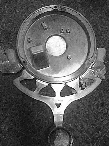
The casting system of this example is designed through comprehensive analysis of the characteristics of the parts and comprehensive consideration of the die casting process. It turns out that the design of this gating system has completely achieved the success of the horse. That is, a trial is successful.
Of course, it is necessary to design each mold. In addition to the above steps, it is necessary to be familiar with the influence of the form and size of the gate and runner on the liquid flow. This is also the determinant of success. one.
Copyright statement: The content of the article is extracted from the network. If there is any infringement, please contact us to delete it!


.png)


.png) +86-574-83036520
+86-574-83036520 +86-574-83008051
 sales@innovaw.com

.png)

.png)
.png)
.png)

.png)
.png)
.png)


.png)

